Setup & Evalatuion

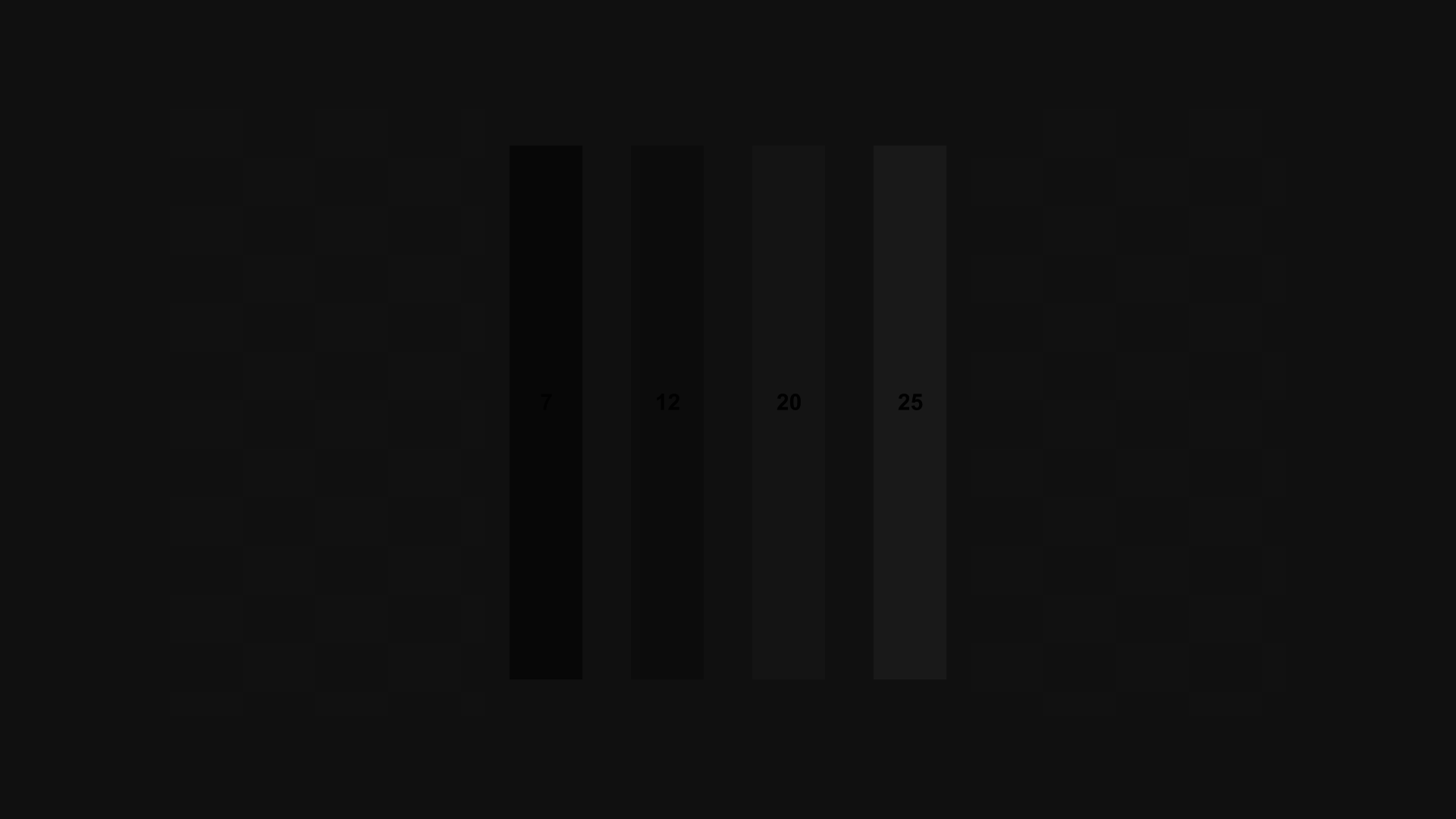
PLUGE Low
PLUGE stands for Picture Line-Up GEnerator, the name of the device that generated patterns similar to this in the early days of television. It is used to set the black level of the display by adjusting the brightness control. First turn up the brightness until all four bars are visible. Then turn the brightness down until the left two bars disappear and the right two bars are still barely visible. If you cannot see the left two bars even if you turn up the brightness, turn down the brightness until the second bar from the right disappears and the far right bar is barely visible, then raise the brightness one notch.
PLUGE High
This is a pattern used to check that the black level looks correct even when there is another bright image on the screen. To set the black level properly, start with the PLUGE Low pattern, then come back to this pattern to verify the black level still looks right.
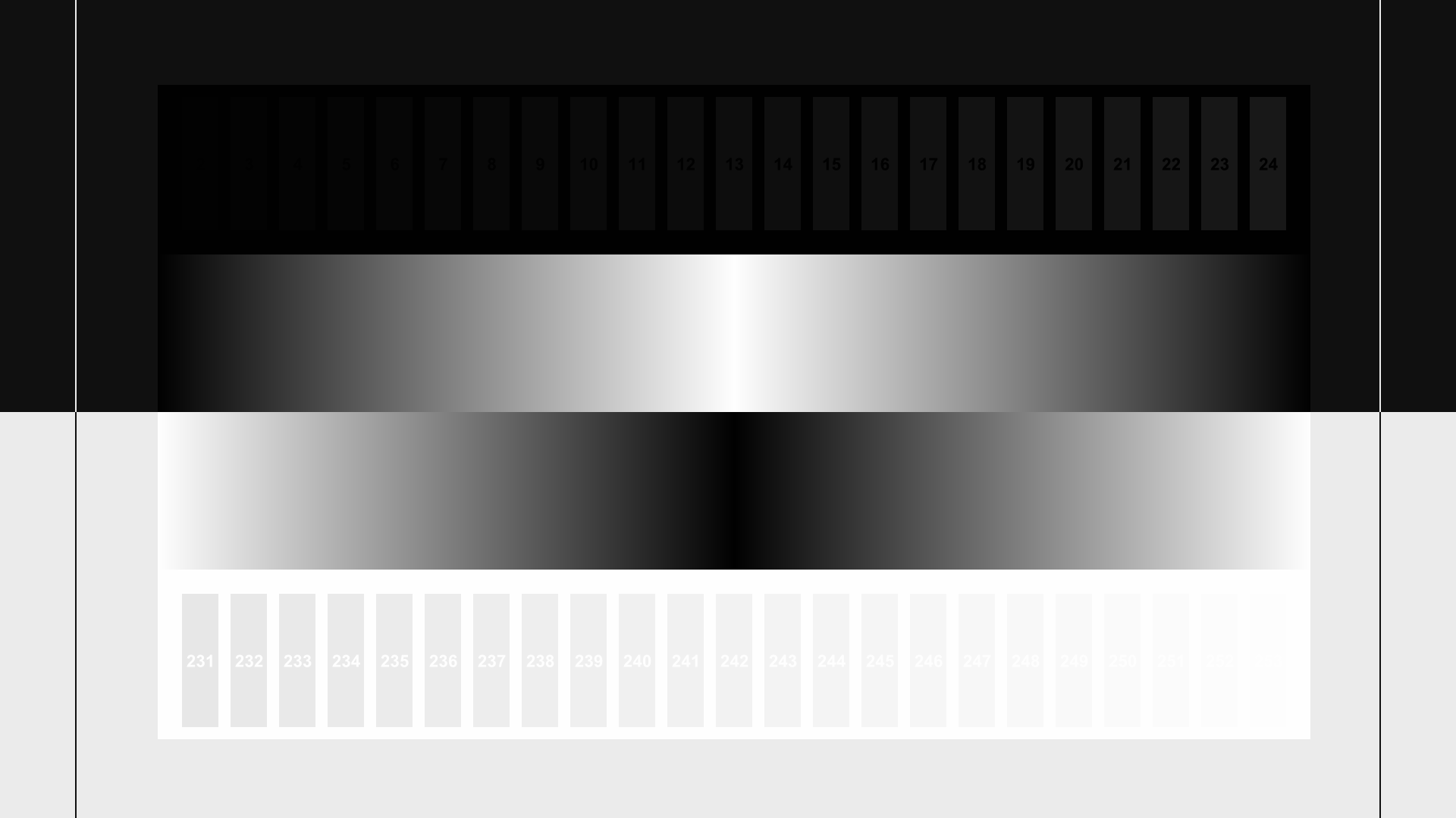
Contrast
This pattern is designed for fine-tuning the settings of the brightness and contrast controls. All of the numbered white bars should be visible and distinct from the surrounding background. The numbered black bars should be distinct from the background starting at bar 17. The ramp that goes from black to white and back should not have an extra-wide center white stripe. The ramp that goes from white to black and back should have a wider black stripe in the center. Both of the center ramps should be smooth and free of visible steps. Note that it may be difficult to see the highest and lowest three or four levels clearly unless you are in a dark room with your eyes fully adjusted to the ambient level.
Color Bars
This pattern is designed for setting the color (sometimes called “picture”) control on the display. This requires a blue filter or the ability to turn off the red and green channels on the display. Look at the display through the filter or with only the blue channel visible and adjust the color control until all of the blue, white, magenta, and cyan bars look as close as possible in brightness. Most displays will not need much, if any, color adjustment. Note: this is no longer the recommended pattern for setting brightness. The best pattern for initial brightness setting is the “PLUGE Low” pattern.
HD Color Bars
This is an alternate color bar pattern designed for modern displays. To set color, look through a blue filter, or put the display in “blue only” mode if available, and adjust the blue, cyan, and magenta bars so they match the brightness of the white bar beneath them. The ramp below the solid white bar should be smooth and free of stairsteps. Note: this is not the recommended pattern for setting brightness. The best pattern for initial brightness setting is the “PLUGE Low” pattern.
Sharpness
This pattern is used to check for sharpening artifacts such as ripples near hard edges. The vertical and horizontal lines should have clean, sharp edges with no ghost lines or bright halos next to them. The circles and diagonal lines should be smooth and free of stairstepping. To set the sharpness control on your display, turn it up until you start to see artifacts, then turn it down until the artifacts just disappear.
Clipping
This pattern is designed to show clipping of the peaks in both the luma channel and the three RGB display channels. Each pattern has concentric squares that range from the reference level to the peak level for luma (white) and the four color channels. A properly adjusted display should be able to reproduce all of the levels. If the patterns all are solid with no visible steps, the display or player is clipping all levels above reference level. If some of the steps look wider than others, the display or player is clipping some of the levels above reference or merging them into one output level. If either of those occurs, try lowering the contrast control just until all levels are distinct and visible, and all of the steps are the same width.
Image Cropping
This pattern is designed to show how much of the image encoded on the disc is visible on screen. It can also be used to center the picture on screen. Look at the top, bottom, left and right for the highest numbered box that is missing the outermost white line near the edge of the screen. That tells you how many pixels are being cropped from that edge. If the outermost line on the box numbered “1” is visible, there is no cropping on that edge. If the outermost line on the box numbered “30” is missing, there is at least 30 pixels of cropping on that edge, and possibly more. If your display has controls that can move the image, move the image up, down, left and right so the amount of cropping is the same on left and right, and the same on top and bottom.
Chroma Alignment
This pattern is designed to test alignment of color channels. To check RGB alignment, look closely at the white crosshairs in the center and corners. If you see color fringes or separate colored lines instead of solid white, then the RGB alignment of the display is incorrect, or the lens is introducing chromatic aberration. To check encoded color channels, look at the colored diamond shapes on the top, bottom, and sides. The colored lines should be exactly centered in the thin diamond shapes. If the colored lines are shifted to the left or right then the chroma channels are misaligned with the luma channels. Every element of this pattern should look symmetrical, with the right side matching the left side and the top matching the bottom.
Dynamic Range High
This pattern is designed to show whether the display is reproducing all the levels above reference white up to peak white. On a properly adjusted display all the bars except the brightest one should be visible and distinct from the background. If they are not, adjust the contrast control until the brightest bar just barely fades into the background, or adjust until the second-brightest bar fades into the background, then raise the contrast control one notch.
Dynamic Range Low
This pattern allows you to check if all of the range possible in the video signal is being sent to the display. Under normal circumstances, only bars 18 and above should be clearly visible, and possibly just barely bar 17. But if you turn the brightness control up, all of the bars should be visible except possibly the darkest bar at the far left (level 2).
NOTE: Do not adjust the display to show all of the bars, except for testing purposes. Only bars 18 and above should be distinct from the background under normal conditions. Only raise the brightness to check that the lower levels are being sent to the display, then lower the brightness again to the correct level.
11 Step Crossed Gray Scale
There are 11 levels from black to white on this chart, and all 11 levels should be clearly visible. The far left and right bars are slightly wider; this is normal. If the borders between the darkest bars aren’t visible, raise the brightness control until you can see the difference between them clearly. Then fine-tune the brightness using the “PLUGE Low” pattern. If the borders between the lightest bars aren’t visible, lower the contrast control until you can see the difference between them clearly. Then use the clipping pattern to fine-tune the contrast control.
Luma Multiburst
This pattern is designed to test the bandwidth of the luma channel. All of the burst patterns should be clear, with the peaks at essentially the same intensity as the stripes on the far left. If the thinnest lines turn gray or are lower in intensity than the rest, then the full resolution of the luma channel is not being reproduced by the display. Note: this is a perfectly normal result for a display that has native resolution lower than 1920×1080.
Chroma Multiburst
This pattern is designed to test the bandwidth of the chroma channels. All of the burst patterns should show clear blue and red stripes, with the peaks at essentially the same intensity as the stripes on the far left. If the thinnest lines turn gray or are lower in color intensity than the rest, then the chroma channels are not being reproduced accurately.
Luma Zone Plate
This pattern is designed to check overall luma resolution and reproduction. The center of the pattern should be clear, bright, and smooth. No stairstepping should appear on the edges of the concentric circles. The peaks should look rounded and not flat or clipped. On the far left and right side, a small amount of stairstepping is normal, as are faint moiré patterns scattered near the edges, which look like a fainter version of the center of the pattern. The stairstepping at the edges of the pattern should be nearly invisible from your seating position. The edges of the pattern should show detail and should not turn gray. Note: if the resolution of your display is less than 1920×1080, the edges of the pattern will be gray and the moiré will be more pronounced. This is normal.
Chroma Zone Plate
This pattern is designed to check overall chroma resolution and reproduction. The center of the pattern should be clear, bright, and smooth. No stairstepping should appear on the edges of the concentric circles. The brightest peaks should look rounded and not flat or clipped. On the far left and right side, a small amount of stairstepping is normal, as is a faint moiré, which looks like a ghost version of the center of the pattern. The moiré should not occupy more than the middle third of the screen, vertically, and the stairstepping at the edges of the pattern should be nearly invisible from your seating position. The brightness and colorfulness of the pattern should be even and consistent all the way out to the edges.
Chroma Upsampling Error
This pattern checks whether the MPEG, VC-1, or AVC decoder in your player is properly upconverting the chroma channel for progressive 4:2:0 content. Look carefully at the diagonal lines. They should be smooth and free of obvious jaggies, steps, or streaks. If there are horizontal streaks or obvious steps in the diagonals, or the patterns appear to shimmer as the clip plays, the decoder is not correctly upsampling the chroma channel.
Geometry
This pattern is designed to facilitate measuring whether the display is distorting the height or width of the picture. Using a tape measure, measure the height and width of the circles and squares. They should be equal. The diagonals in the center should also be equal length.
Source Adaptive Deinterlacing
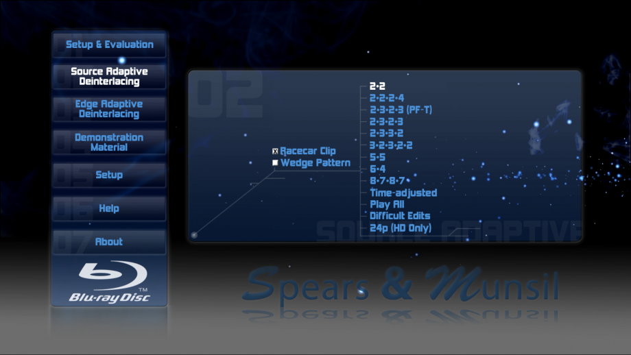
Wedge Pattern
This clip is designed to check overall deinterlacing performance. As the wedges move, the narrow end of the horizontal wedge should have clear alternating black and white lines rather than blurry or flickering lines. There should be moiré only in the last quarter or less of the wedges, just near the tips. The overall brightness of the wedge should be the same across the entire length. Both wedges should remain steady and not flicker for the length of the clip.
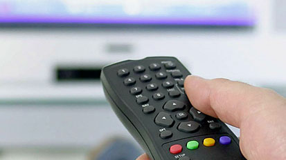
Racecar Clip
This clip is designed to check overall deinterlacing performance. As the car moves across the screen, the bleachers in the background should be detailed and free of obvious moiré. They should remain steady at all times and not flicker for the entire length of the clip.
2•2:
The cadence of this clip is 2-2, meaning that there are 2 fields (1 frame) of each image. This is equivalent to 30 frames per second, which is commonly used in computer graphics rendered for video and in some high-speed camera footage.
2•2•2•4:
The cadence of this clip is 2-2-2-4, which is 2 fields (1 frame) of each of the first three images, then 4 fields (2 frames) of the fourth image, repeating to the end of the clip. This cadence is a less common way of converting 24p film to 60i video, used occasionally for film transfers and on some camcorders that have a “film look” mode.
2•3•2•3 (PF-T):
The cadence of this clip is 2-3-2-3, which is 2 fields (1 frame) of the first image, then 3 fields (one frame plus one field) of the next image, repeating to the end of the clip. This cadence is the most common one used for transferring 24p film to 60i video. This version of the clip is encoded using individual progressive frames, which is more commonly used in professional film encoding. This version should produce results identical to the alternate version which uses interlaced frames.
2•3•2•3:
The cadence of this clip is 2-3-2-3, which is 2 fields (1 frame) of the first image, then 3 fields (1 frame plus 1 field) of the next image, repeating to the end of the clip. This cadence is the most common one used for transferring 24p film to 60i video. This version of the clip is encoded using interlaced fields, which is somewhat less commonly used in professional film encoding. This version should produce results identical to the standard version which uses progressive frames.
2•3•3•2:
The cadence of this clip is 2-3-3-2, which is 2 fields (1 frame) of the first image, then 3 fields (1 frame plus 1 field) of the next image, then 3 fields of the next, then 2 fields of the next, repeating to the end of the clip. This cadence is used by a few camcorders that have a 24p “film look” mode.
3•2•3•2•2:
The cadence of this clip is 3-2-3-2-2, which is 3 fields (1 frame plus 1 field) of the first image, then 2 fields (1 frame) of the next image, then 3 fields of the next, then 2 fields of the next, then 2 fields of the next, repeating to the end of the clip. This cadence can occur when film is transferred at slightly higher-than-normal speed, usually to condense a film for time.
5•5:
The cadence of this clip is 5-5, which is 5 fields (2 frames plus 1 field) each image. This cadence is the most common one used when 12 fps animation (often used in TV shows), is transferred to 60i video.
6•4:
The cadence of this clip is 6-4, which is 6 fields (3 frames) of the first image, then 4 fields (2 frames) of the next image, repeating to the end of the clip. This cadence is a less common pattern used when 12 fps animation (often used in TV shows), is transferred to 60i video.
8•7•8•7:
The cadence of this clip is 8-7-8-7, which is 8 fields (4 frames) of the first image, then 7 fields (3 frames plus 1 field) of the next image, repeating to the end of the clip. This cadence is most commonly used when 8 fps animation (often used for Japanese anime), is transferred to 60i video.
24p:
This clip is encoded as true 24 fps progressive, and any cadence used to convert the 24 fps content to the native display rate is being done by the player or display. If your player is outputting 24p video, and your display can display it at 24 fps or a simple multiple of 24 (like 48 or 72 fps), you should see smooth motion with no stuttering or hitching.
Difficult edits
This clip is representative of material that was originally shot on film, but edited on video. Within each section, the 2-3 pulldown cadence is perfect, but just before and/or just after every other edit, the pattern is slightly different. All film frames have been encoded with at least 2 fields, so a good deinterlacer should be able to reconstruct each original film frame and stay in film mode at each edit. The image should retain all its resolution and not show any moiré or artifacts.
Time-adjusted
This clip was originally transferred using standard 2-3-2-3 cadence, then sped up by a small amount by dropping a field every half-second or so. This causes the cadence to “break” regularly. A good deinterlacer should play the clip in film mode with no flickering, and it should look essentially identical to the 2-3-2-3 cadence clips.
Edge Adaptive Deinterlacing
Jaggies
This clip is designed to evaluate the player or display’s ability to deinterlace true video content without distracting jagged stairstep patterns on edges. Look at the diagonal edges of the bar as it rotates. They should look clean and not obviously jagged. In addition, the alternating black and white lines should stay solid and not flicker or turn solid white, black, or gray. There may be thin gray or black borders next to the solid white line where it passes through the alternating black and white horizontal lines. Different deinterlacers will have slightly different results on this test. The two samples shown here represent the extremes from best to worst.
Bridge
This clip is designed to evaluate the player or display’s ability to deinterlace true video content without distracting jagged stairstep patterns on edges. Look at the diagonals on the bridge cables. They should be smooth and solid, and not look like stairsteps or a dashed line. The diagonals on the flag should be smooth and not stairstepped.
Hockey
This clip is designed to evaluate the player or display’s ability to deinterlace true video content without distracting jagged stairstep patterns on edges. Look at the diagonal edges of the top of the glass in the foreground, the lines on the ice, and the edge of the rink in the background. They should be smooth and not jagged or stairstepped.
Ropes
This clip is designed to evaluate the player or display’s ability to deinterlace true video content without distracting jagged stairstep patterns on edges. Look at the thin ropes, especially the ones that are nearly horizontal. They should be smooth and solid looking, not jagged, stairstepped, or broken into small segments.
Ship
This clip is designed to evaluate the player or display’s ability to deinterlace true video content without distracting jagged stairstep patterns on edges. Look at the thin ropes that crisscross the ship, especially the ones that are close to horizontal, and the yellow trim on the side of the ship. They should be smooth and solid looking, not jagged, stairstepped, or broken into small segments.
Mixed Film & Video
This clip is designed to test the ability of the deinterlacer to handle a composite image with two different cadences overlaid on each other. In this case, a film-cadence clip has scrolling text over it that is interlaced. A good deinterlacer will recognize that the text is video encoded and stay in video mode. A bad deinterlacer will lock on to the cadence of the main video and cause the text to comb badly.
Demonstration Material
Montage
This is 24p content, shot with an ultra-high-resolution digital cinema camera. The detail and definition of these clips is as high as you can get, and can be used as reference material to demonstrate your system, and to compare overall quality of different players and displays. On a player that is configured to output 24p and a display with the ability to display 24, 48, or 72 fps, the pans and zooms should be smooth and free of any hitches or stutters. The clouds and whitecaps should have clear detail and should not be clipped or posterized.